Wednesday, June 12, 2013
Transistor Ignition circuit Schematic with explanation
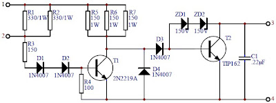
This transistor ignition circuit give your car to have better starting and smoother running, particularly at very high and very low RPM. Lower fuel consumption, less pollution, lower servicing costs. Drive economically, drive electronically. Only for petrol/gasoline engines. This circuit will reduce breaker point wear and provide cleaner spark.
Circuit diagram:

Wiring diagram with the vehicles:
Notes:
This circuit used for cars with negative ground 12V negative ground system, maximum ignition current of 4A and maximum switching speed 500KHz. Motorcycles, mowers, boats, etc can also use this circuit.
For 6V Negative ground system, change the following resistors:
- R1, R2: 150 ohm / 1W
- R3 : 68 ohm / 1/4W
- R4 : 100 ohm / 1/4W
- R5, R6, R7: 68 ohm / 1W
The kit of Electronic Transistor Ignition is available at electronickits.com, sell at $25.95.
Download the manual Transistor Ignition kit HERE
Tuesday, June 4, 2013
Fuse Box Diagram Mercedes Benz CLK 320 2001


Fuse Panel Layout Diagram Parts: control module box, relay module, air
pump, blower motor, CFI control module, traction system control module,
data link connector