Wednesday, June 12, 2013
Transistor Ignition circuit Schematic with explanation
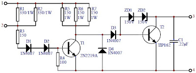
This transistor ignition circuit give your car to have better starting and smoother running, particularly at very high and very low RPM. Lower fuel consumption, less pollution, lower servicing costs. Drive economically, drive electronically. Only for petrol/gasoline engines. This circuit will reduce breaker point wear and provide cleaner spark.
Circuit diagram:

Wiring diagram with the vehicles:
Notes:
This circuit used for cars with negative ground 12V negative ground system, maximum ignition current of 4A and maximum switching speed 500KHz. Motorcycles, mowers, boats, etc can also use this circuit.
For 6V Negative ground system, change the following resistors:
- R1, R2: 150 ohm / 1W
- R3 : 68 ohm / 1/4W
- R4 : 100 ohm / 1/4W
- R5, R6, R7: 68 ohm / 1W
The kit of Electronic Transistor Ignition is available at electronickits.com, sell at $25.95.
Download the manual Transistor Ignition kit HERE
Tuesday, June 4, 2013
Fuse Box Diagram Mercedes Benz CLK 320 2001


Fuse Panel Layout Diagram Parts: control module box, relay module, air
pump, blower motor, CFI control module, traction system control module,
data link connector
Friday, May 31, 2013
Wire Diagrams
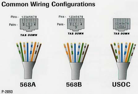
Cat 5 Rj 45 Wire Diagrams.

Rj 45 Cables Jpg.

Connector Ez Rj45 Connector 50 Pkg Platinum Tools Tmt 06 150003.

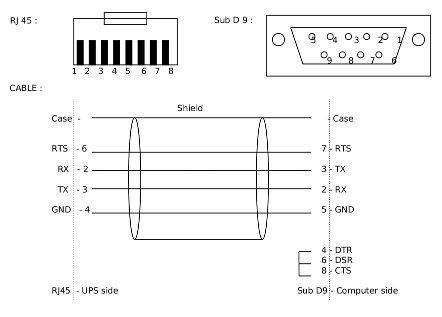
Serial Connection Db9 To Rj45.
Rj45 Wiring 568a.
We Use Red Cable For Crossed Cables Note All Our Crossed Wiring Is.

Nameless Wireless Network Ultrawap Poe Modification.
Network Ups Tools Cables.

Rj45 How To Make A Network Cable.

Here Is A Decent Picture Of Proper Rj45 Wiring.
Sunday, May 19, 2013
Automatic Fan Controller
and all worked fine after replacing the trimmer pot. The one used in the above circuit diagram was a 50K model. This 50K was measured at exactly 25 °C and with 10% tolerance.
The resistance increases as the surrounding temperature decreases. Tolerance for my application (cooling a large powersupply coolrib) is 10%. Another name for this thing is NTC. NTC stands for "Negative Temperature Coefficient" which means when the surrounding temperature decreases the resistance of this thermistor will increase. I replaced my thermistor for a 60K hermetically
sealed glass type since the environment for my application may contain corrosive particles which may affect performance on a future date. P1 is a regular Bourns trimmer and adjusts a wide range of temperatures for this circuit.
I used the 10-turn type for a bit finer adjustment but the regular type will work for your application.
R1 is a security resistor just in case the trimmer pot P1 is adjusted all the way to 0 ohms. At which time the thermistor would get the full 12 volt and it will get so hot that it puts blisters on your fingers... :-)
R3 feeds a bit of hysteresis back into the op-amp to eliminate relay chatter when the temperature of the thermistor reaches its threshold point. Depending on your application and the type you use for Q1 and Re1, start with 330K or so and adjust its value downwards until your satisfied. The value of 150K shown in the diagram worked for me. Decreasing the value of R2 means more hysteresis, just dont use more then necessary. Or temporarily use a trimmer pot and read off the value. 120K worked for me.
 Transistor Q1 can be a 2N2222(A), 2N3904, NTE123A, ECG123A, etc. Not critical at all. It acts only as a switch for the relay so almost any type will work, as long as it can provide the current needed to activate the relays coil. D1, the 1N4148, acts as a spark arrestor when the contacts of the relay open and eliminates false triggering. For my application the 1N4148 was good enough since the tiny relay I used was only 1 amp.
 However, you can use a large variety of diodes here, my next choice would be a regular purpose 1N4001 or something and should be used if your relay type can handle more then 1 amp. If you like to make your own pcb, try the one above. The pcb is fitted with holes for the relay but may not fit your particular relay. It was designed for a Aromat HB1-DC12V type.
The variety and model of relays is just to great. How to mount it then? Well, I left ample space on the pcb to mount your relay. You can even mount it up-side-down and connect the wires individually. Use Silicon glue, cyanoacrylate ester (crazy glue), or double-sided tape to hold the relay in place. Works well. Note that the pcb and layout is not according to the circuit diagram in regards to the hookup of the fans. The PCB measures approximately 1.5 x 3 inches (4.8 x 7.6mm) If you print the pcb to an inkjet printer it is probably not to scale. Try to fit a 8-pin ic socket on the printed copy to make sure it fits before making the pcb...
Friday, May 17, 2013
6 Line Digital Wireless Systems XDS PLUS
 6 Line Digital Wireless Systems XDS-PLUS
The XDS-PLUS is a asperous agenda apparatus wireless arrangement antic abounding appearance of the XDR Series arranged into a metal anatomy stompbox receiver. The result: continued abundance acknowledgment and continued operating ambit that alone a Line 6 can accord you.
The XDS-PLUS appearance companderless technology and bifold agenda manual for the complete and feel of a absolute wire affiliation with an absurd akin of arrest aegis alone accessible from Line 6.
MelodyMusicOnline is an Authorized Line 6 Digital Wireless Dealer
Visit the Line 6 Web Site much more information
Features include:
• Dual RF Diversity (anti-jamming)
• Continental Roaming
• 200’ Operating Range
• 2009 Compliant so it’s Free from FCC & DTV Concerns
• Metal Stompbox Receiver with 1/4 Wave Detachable Antenna
SYSTEM CONTAINS:
• XDT4 Digital UHF bodypack transmitter
• XDR2 Digital UHF stompbox receiver
• Instrument cable
• 9V DC Power supply included
• Users guide and all necessary batteries
SPECIFICATIONS:
Frequency Response (± .5dB):
10 Hz – 20 kHz
Audio Dynamic Range:
Greater than 118 dB
Distortion:
0.03% THD
Compatible Channels:
Five
RF Output Power:
15mw
Operating Range:
200′ line-of-sight (may vary due to local conditions)