Sunday, March 31, 2013
LED Music Level Indicator Circuit Diagram
The shown LEDs in the circuit sequentially light and "dance" as per the level of the music applied at the input, preferable directly from the speaker terminals of the audio gadget whose music level is to be monitored.
The circuit may be understood as follows:
The components which support the LED illumination are the associated NPN transistor, the emitter resistor, the base preset and the corresponding diode.
The above stage is identical to all the LEDs included in the circuit for obtaining the desired push-pull effect in response to the applied music level at the input.
However theres one difference between the LED stages, though most of the component placement is similar, the diodes form a different pattern.
If you see the circuit closely you will find that the the ground to the first transistor/LED stage from left comes across only a single diode, however the preceding stages ground potential has to encounter the extra corresponding number of diodes in theor path.
As we all know that a diode has the property of dropping 0.6 volts, means that the first transistor would conduct much sooner than the second, the second transistor conducts sooner than the third and so on.
Because as the number of diodes increase in the path of the respective transistor, the conduction is inhibited until the the voltage sufficiently increases for bypassing the diodes overall forward voltage.
This increase in voltage can happen only when the pitch of the music increases, giving rise to a sequentially running LED bar graph which shoots forward in response to the pitch or loudness o the applied input music.
The transistor at the input is a PNP and complements the rest of the transistors employed for illuminating the LEDs. The PNP transistor at the input amplifies the applied low level music sinal to levels which is just enough for illuminating the LEDs with reference to the music levels,.
Parts List
All NPN Transistors are BC547,
PNP Transistor is BC557,
All Presets are 10K,
All resistors are 100Ohm,
LEDs as per choice
LED Music Level Indicator Circuit Diagram
Friday, March 29, 2013
AC Power Supply Low Voltage
This is an AC power supply circuit with low voltage output (step down transformer converter). Notes! This project involves the use of dangerous voltages. You must make sure all high-voltage (120 volt household power) conductors are safely insulated from accidental contact. No bare wires should be seen anywhere on the “primary” side of the transformer circuit. Be sure to solder all wire connections so that they’re secure, and use real electrical tape (not duct tape, scotch tape, packing tape, or any other kind!) to insulate your soldered connections. If you wish to enclose the transformer inside of a box, you may use an electrical “junction” box, obtained from a hardware store or electrical supply house. If the enclosure used is metal rather than plastic, a three-prong plug should be used, with the “ground” prong (the longest one on the plug) connected directly to the metal case for maximum safety.


Before plugging the plug into a wall socket, do a safety check with an ohmmeter. With the line switch in the “on” position, measure resistance between plug prong and the transformer case. There should be infinite (maximum) resistance. If the meter registers continuity (some resistance value less than infinity), then you have a “short” between one of the power conductors and the case, which is dangerous!
Next, check the transformer windings themselves for continuity. With the line switch in the “on” position, there should be a small amount of resistance between the two plug prongs. When the switch is turned “off,” the resistance indication should increase to infinity (open circuit — no continuity). Measurement the resistance between pairs of wires is on the secondary side. These secondary windings should register much lower resistances than the primary. Why is this?
Plug the cord into a wall socket and turn the switch on. You should be able to measure AC voltage at the secondary side of the transformer, between pairs of terminals. Between two of these terminals, you should measure about 12 volts. Between either of these two terminals and the third terminal, you should measure half that. This third wire is the “center-tap” wire of the secondary winding.
Wednesday, March 27, 2013
Fuse Box Toyota 1997 Camry CE Diagram
Fuse Box Toyota 1997 Camry CE Diagram - Here are new post for Fuse Box Toyota 1997 Camry CE Diagram.

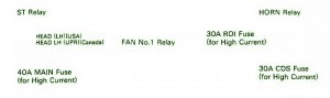
Fuse Panel Layout Diagram Parts: engine main relay, horn relay, RDI fuse, CDS fuse, headlamp, head relay, St relay, main fuse-high current, EFI relay.
Full Article here..
Fuse Box Toyota 1997 Camry CE Diagram


Fuse Panel Layout Diagram Parts: engine main relay, horn relay, RDI fuse, CDS fuse, headlamp, head relay, St relay, main fuse-high current, EFI relay.
Monday, March 25, 2013
TL072 Op Amp based 11 90 hz Subwoofer Filter
 TL072 Op-Amp based 11-90 hz Subwoofer Filter
 TL072 Op-Amp
The circuit subwoofer filter allows the addition of subwoofers to an existing full-range system, offering adjustable low-pass filter with the option of momentum and R6 and R8 mono-summary.
The subwoofer filter to remove separate preamplifier circuit to drive the low frequency sound a lot. At the tone, dial tone and can not be normal to do ... is a fine deep low bass sounds like a drum, or a cinema complex in a low voice if you can listen but to add cabinets and amplifiers. Subwoofer circuit is low-pass frequency of 11-90 Hz switching power supply 12V court if necessary to use +-15V. I changed the capacitor to cut the voice by a red circle mark.
The subwoofer filter to remove separate preamplifier circuit to drive the low frequency sound a lot. At the tone, dial tone and can not be normal to do ... is a fine deep low bass sounds like a drum, or a cinema complex in a low voice if you can listen but to add cabinets and amplifiers. Subwoofer circuit is low-pass frequency of 11-90 Hz switching power supply 12V court if necessary to use +-15V. I changed the capacitor to cut the voice by a red circle mark.
Saturday, March 23, 2013
Flugzeugepiper Saratoga

Piper Aircraft Unveils The Piper Matrix A Cabin Class Six Seat.

Full Piper Aircraft Library.

Piper Aircraft Corporation Pa 28r 201.

Flugzeuge De Piper 28 Rt.

Piper Aircraft.

Piper Colt A Two Place Bargain Aircraft Market Place.

Piper Warrior Iii Personal Sport Aircraft Travel Gadgets.

Flugzeuge De Piper Saratoga Ii Hp.

Flugzeuge De Piper Pa 30 N7311y.

Flugzeuge De Piper P28 T Cockpit.
Thursday, March 21, 2013
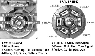
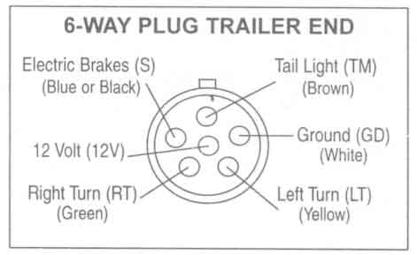
Trailer Wiring Connector Diagrams Conductor Plugs

Trailer Wiring Sop.

Trailer Light Wiring Typical Trailer Light Wiring Diagram.

Trailer Wiring.
Troubleshooting Trailer Wiring.

For A Trailer Plug And Tow Bar Socket Wiring Diagram.

Http Www Tridenttrailers Com Trailer Wiring Diagram Htm For Britain.

Trailer Wiring.
Trailer Wiring Diagrams Johnson Trailer Sales Colfax Wisconsin.

Pn Trailer Wiring.

Trailer Wiring Connector Diagrams For 6 7 Conductor Plugs.
Subscribe to:
Posts (Atom)