Wednesday, June 12, 2013
Transistor Ignition circuit Schematic with explanation
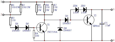
This transistor ignition circuit give your car to have better starting and smoother running, particularly at very high and very low RPM. Lower fuel consumption, less pollution, lower servicing costs. Drive economically, drive electronically. Only for petrol/gasoline engines. This circuit will reduce breaker point wear and provide cleaner spark.
Circuit diagram:

Wiring diagram with the vehicles:
Notes:
This circuit used for cars with negative ground 12V negative ground system, maximum ignition current of 4A and maximum switching speed 500KHz. Motorcycles, mowers, boats, etc can also use this circuit.
For 6V Negative ground system, change the following resistors:
- R1, R2: 150 ohm / 1W
- R3 : 68 ohm / 1/4W
- R4 : 100 ohm / 1/4W
- R5, R6, R7: 68 ohm / 1W
The kit of Electronic Transistor Ignition is available at electronickits.com, sell at $25.95.
Download the manual Transistor Ignition kit HERE
Tuesday, June 4, 2013
Fuse Box Diagram Mercedes Benz CLK 320 2001


Fuse Panel Layout Diagram Parts: control module box, relay module, air
pump, blower motor, CFI control module, traction system control module,
data link connector
Friday, May 31, 2013
Wire Diagrams
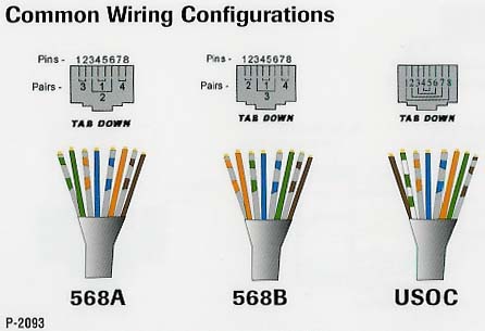
Cat 5 Rj 45 Wire Diagrams.

Rj 45 Cables Jpg.

Connector Ez Rj45 Connector 50 Pkg Platinum Tools Tmt 06 150003.

Serial Connection Db9 To Rj45.
Rj45 Wiring 568a.
We Use Red Cable For Crossed Cables Note All Our Crossed Wiring Is.

Nameless Wireless Network Ultrawap Poe Modification.
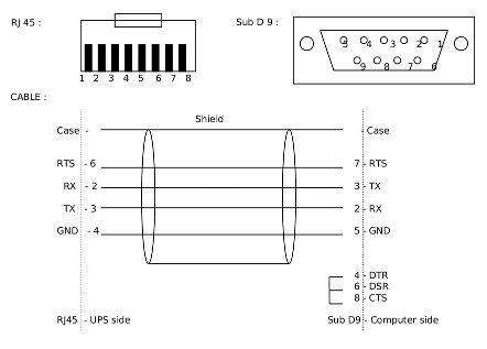
Network Ups Tools Cables.

Rj45 How To Make A Network Cable.

Here Is A Decent Picture Of Proper Rj45 Wiring.
Sunday, May 19, 2013
Automatic Fan Controller
and all worked fine after replacing the trimmer pot. The one used in the above circuit diagram was a 50K model. This 50K was measured at exactly 25 °C and with 10% tolerance.
The resistance increases as the surrounding temperature decreases. Tolerance for my application (cooling a large powersupply coolrib) is 10%. Another name for this thing is NTC. NTC stands for "Negative Temperature Coefficient" which means when the surrounding temperature decreases the resistance of this thermistor will increase. I replaced my thermistor for a 60K hermetically
sealed glass type since the environment for my application may contain corrosive particles which may affect performance on a future date. P1 is a regular Bourns trimmer and adjusts a wide range of temperatures for this circuit.
I used the 10-turn type for a bit finer adjustment but the regular type will work for your application.
R1 is a security resistor just in case the trimmer pot P1 is adjusted all the way to 0 ohms. At which time the thermistor would get the full 12 volt and it will get so hot that it puts blisters on your fingers... :-)
R3 feeds a bit of hysteresis back into the op-amp to eliminate relay chatter when the temperature of the thermistor reaches its threshold point. Depending on your application and the type you use for Q1 and Re1, start with 330K or so and adjust its value downwards until your satisfied. The value of 150K shown in the diagram worked for me. Decreasing the value of R2 means more hysteresis, just dont use more then necessary. Or temporarily use a trimmer pot and read off the value. 120K worked for me.
 Transistor Q1 can be a 2N2222(A), 2N3904, NTE123A, ECG123A, etc. Not critical at all. It acts only as a switch for the relay so almost any type will work, as long as it can provide the current needed to activate the relays coil. D1, the 1N4148, acts as a spark arrestor when the contacts of the relay open and eliminates false triggering. For my application the 1N4148 was good enough since the tiny relay I used was only 1 amp.
 However, you can use a large variety of diodes here, my next choice would be a regular purpose 1N4001 or something and should be used if your relay type can handle more then 1 amp. If you like to make your own pcb, try the one above. The pcb is fitted with holes for the relay but may not fit your particular relay. It was designed for a Aromat HB1-DC12V type.
The variety and model of relays is just to great. How to mount it then? Well, I left ample space on the pcb to mount your relay. You can even mount it up-side-down and connect the wires individually. Use Silicon glue, cyanoacrylate ester (crazy glue), or double-sided tape to hold the relay in place. Works well. Note that the pcb and layout is not according to the circuit diagram in regards to the hookup of the fans. The PCB measures approximately 1.5 x 3 inches (4.8 x 7.6mm) If you print the pcb to an inkjet printer it is probably not to scale. Try to fit a 8-pin ic socket on the printed copy to make sure it fits before making the pcb...
Friday, May 17, 2013
6 Line Digital Wireless Systems XDS PLUS
 6 Line Digital Wireless Systems XDS-PLUS
The XDS-PLUS is a asperous agenda apparatus wireless arrangement antic abounding appearance of the XDR Series arranged into a metal anatomy stompbox receiver. The result: continued abundance acknowledgment and continued operating ambit that alone a Line 6 can accord you.
The XDS-PLUS appearance companderless technology and bifold agenda manual for the complete and feel of a absolute wire affiliation with an absurd akin of arrest aegis alone accessible from Line 6.
MelodyMusicOnline is an Authorized Line 6 Digital Wireless Dealer
Visit the Line 6 Web Site much more information
Features include:
• Dual RF Diversity (anti-jamming)
• Continental Roaming
• 200’ Operating Range
• 2009 Compliant so it’s Free from FCC & DTV Concerns
• Metal Stompbox Receiver with 1/4 Wave Detachable Antenna
SYSTEM CONTAINS:
• XDT4 Digital UHF bodypack transmitter
• XDR2 Digital UHF stompbox receiver
• Instrument cable
• 9V DC Power supply included
• Users guide and all necessary batteries
SPECIFICATIONS:
Frequency Response (± .5dB):
10 Hz – 20 kHz
Audio Dynamic Range:
Greater than 118 dB
Distortion:
0.03% THD
Compatible Channels:
Five
RF Output Power:
15mw
Operating Range:
200′ line-of-sight (may vary due to local conditions)
Sunday, May 5, 2013
Make a Photodiode Alarm Diagram
The circuit uses a PN Photodiode in the reverse bias mode to detect light intensity. In the presence of Laser / IR rays, the Photodiode conducts and provides base bias to T1. The NPN transistor T1 conducts and takes the reset pin 4 of IC1 to ground potential. IC1 is wired as an Astable oscillator using the components R3, VR1 and C3. The Astable operates only when its resent pin becomes high. When the Laser / IR beam breaks, current thorough the Photodiode ceases and T1 turns off. The collector voltage of T1 then goes high and enables IC1. The output pulses from IC1 drives the speaker and alarm tone will be generated.
Photo-Diode Alarm Circuit


Tuesday, April 30, 2013
Particularly LM317 Circuit With 12v Battery Charger Circuit
The LM317 is AN adjustable three terminal transformer that is capable of supply 1.2 to 37 volts with a secure 1.5A output current. The LM317 is prepackaged terribly} normal electronic transistor package that makes it very simple to mount in your circuits.

In addition to higher performance than mounted regulators, the LM317 series offers full overload protection out there solely in ICs. enclosed on the chip square measure current limit, thermal overload protection and safe space protection.
The LM317 makes AN particularly easy adjustable change regulator, a programmable output regulator, or by connecting a set electrical device between the adjustment pin and output, the LM317 may be used as a preciseness current regulator. provides with electronic conclusion may be achieved by clamping the adjustment terminal to ground that programs the output to one.2V wherever most masses draw very little current.


Specifications
- Guaranteed 1% output voltage tolerance (LM317A)
- Guaranteed max. 0.01%/V line regulation (LM317A)
- Guaranteed max. 0.3% load regulation (LM117)
- Guaranteed 1.5A output current
- Adjustable output down to 1.2V
- Current limit constant with temperature
- P + Product Enhancement tested
- 80 dB ripple rejection
- Output is short-circuit protected

Circuit
Once you have learnt enough you can now put the LM317 into use and make the following circuit:
Overview
Pin one of the LM317 IC is that the management pin that is employed to manage the charging voltage, Pin a pair of is that the output at that the charging voltage seems, Pin three is that the input to that the regulated DC offer is given.
The charging voltage and current is controlled by the electronic transistor (Q1), electrical device (R1) and POT (VR1). once the battery is 1st connected to the charging terminals, the present through R1 will increase. This successively will increase the present and voltage from LM317. once the battery is totally charged the charger reduces the charging current and also the battery are charged within the trickle charging mode.

Notes
- The input voltage to the circuit should be a minimum of 3V more than the expected output voltage. luminous flux unit 317 dissipates around 3V throughout its operation. Here I used 18V DC because the input.
- The charging voltage may be set by victimization the POT (VR1).
- The luminous flux unit 317 should be mounted on a sink.
- All capacitors should be rated a minimum of 25V.
- Youll be able to use crocodilian clips for connecting the battery to the charger.
Friday, April 12, 2013
Power Supply with tube
 |
| Power Supply with tube |
Wednesday, April 10, 2013
USB Switch Schematic Circuit


Monday, April 8, 2013
12KV High Voltage Generator

Saturday, April 6, 2013
Mains Frequency Monitor
Circuit diagram:

Thursday, April 4, 2013
200 Watt Stereo Car Amplifier
Audio amplifier circuit can work at a minimum voltage 12-volt DC, if supplied under voltage 12-volt amplifier work will be less than the maximum. This amplifier output power up to 200W or 2 x 100W stereo with 8 ohm impedance.

R1 =1K
R2 =50K trim
R3 =1K
R4 =50K trim
R5 =680R
R6 =680R
R7 =150K
R8 =2R2
R9 =2R2
R10=2R2
R11=2R2
Capacitor
C1 =1uF
C2 =1uF
C3 =47uF
C4 =47uF
C5 =100n/400V
C6 =220uF
C7 =220uF
C8 =100n/400V
C9 =100n/400V
C10=100n/400V
Intregated Circuit
IC1=TA8210AH
Connector
X2-3=in R
X2-2=gnd
X2-1=in L
X1-1,X1-2=Out R
X1-3,X1-4=Out L
Tuesday, April 2, 2013
Lights On Diagram Guide

Sunday, March 31, 2013
LED Music Level Indicator Circuit Diagram
The circuit may be understood as follows:
The components which support the LED illumination are the associated NPN transistor, the emitter resistor, the base preset and the corresponding diode.
The above stage is identical to all the LEDs included in the circuit for obtaining the desired push-pull effect in response to the applied music level at the input.
However theres one difference between the LED stages, though most of the component placement is similar, the diodes form a different pattern.
If you see the circuit closely you will find that the the ground to the first transistor/LED stage from left comes across only a single diode, however the preceding stages ground potential has to encounter the extra corresponding number of diodes in theor path.
As we all know that a diode has the property of dropping 0.6 volts, means that the first transistor would conduct much sooner than the second, the second transistor conducts sooner than the third and so on.
Because as the number of diodes increase in the path of the respective transistor, the conduction is inhibited until the the voltage sufficiently increases for bypassing the diodes overall forward voltage.
This increase in voltage can happen only when the pitch of the music increases, giving rise to a sequentially running LED bar graph which shoots forward in response to the pitch or loudness o the applied input music.
The transistor at the input is a PNP and complements the rest of the transistors employed for illuminating the LEDs. The PNP transistor at the input amplifies the applied low level music sinal to levels which is just enough for illuminating the LEDs with reference to the music levels,.
Parts List
All NPN Transistors are BC547,
PNP Transistor is BC557,
All Presets are 10K,
All resistors are 100Ohm,
LEDs as per choice
LED Music Level Indicator Circuit Diagram

Friday, March 29, 2013
AC Power Supply Low Voltage
This is an AC power supply circuit with low voltage output (step down transformer converter). Notes! This project involves the use of dangerous voltages. You must make sure all high-voltage (120 volt household power) conductors are safely insulated from accidental contact. No bare wires should be seen anywhere on the “primary” side of the transformer circuit. Be sure to solder all wire connections so that they’re secure, and use real electrical tape (not duct tape, scotch tape, packing tape, or any other kind!) to insulate your soldered connections. If you wish to enclose the transformer inside of a box, you may use an electrical “junction” box, obtained from a hardware store or electrical supply house. If the enclosure used is metal rather than plastic, a three-prong plug should be used, with the “ground” prong (the longest one on the plug) connected directly to the metal case for maximum safety.


Next, check the transformer windings themselves for continuity. With the line switch in the “on” position, there should be a small amount of resistance between the two plug prongs. When the switch is turned “off,” the resistance indication should increase to infinity (open circuit — no continuity). Measurement the resistance between pairs of wires is on the secondary side. These secondary windings should register much lower resistances than the primary. Why is this?
Plug the cord into a wall socket and turn the switch on. You should be able to measure AC voltage at the secondary side of the transformer, between pairs of terminals. Between two of these terminals, you should measure about 12 volts. Between either of these two terminals and the third terminal, you should measure half that. This third wire is the “center-tap” wire of the secondary winding.
Wednesday, March 27, 2013
Fuse Box Toyota 1997 Camry CE Diagram
Fuse Box Toyota 1997 Camry CE Diagram


Fuse Panel Layout Diagram Parts: engine main relay, horn relay, RDI fuse, CDS fuse, headlamp, head relay, St relay, main fuse-high current, EFI relay.
Monday, March 25, 2013
TL072 Op Amp based 11 90 hz Subwoofer Filter
 TL072 Op-Amp based 11-90 hz Subwoofer Filter
 TL072 Op-Amp
The subwoofer filter to remove separate preamplifier circuit to drive the low frequency sound a lot. At the tone, dial tone and can not be normal to do ... is a fine deep low bass sounds like a drum, or a cinema complex in a low voice if you can listen but to add cabinets and amplifiers. Subwoofer circuit is low-pass frequency of 11-90 Hz switching power supply 12V court if necessary to use +-15V. I changed the capacitor to cut the voice by a red circle mark.
Saturday, March 23, 2013
Flugzeugepiper Saratoga

Piper Aircraft Unveils The Piper Matrix A Cabin Class Six Seat.

Full Piper Aircraft Library.

Piper Aircraft Corporation Pa 28r 201.

Flugzeuge De Piper 28 Rt.

Piper Aircraft.

Piper Colt A Two Place Bargain Aircraft Market Place.

Piper Warrior Iii Personal Sport Aircraft Travel Gadgets.

Flugzeuge De Piper Saratoga Ii Hp.

Flugzeuge De Piper Pa 30 N7311y.

Flugzeuge De Piper P28 T Cockpit.
Thursday, March 21, 2013
Trailer Wiring Connector Diagrams Conductor Plugs

Trailer Wiring Sop.

Trailer Light Wiring Typical Trailer Light Wiring Diagram.

Trailer Wiring.
Troubleshooting Trailer Wiring.

For A Trailer Plug And Tow Bar Socket Wiring Diagram.

Http Www Tridenttrailers Com Trailer Wiring Diagram Htm For Britain.

Trailer Wiring.
Trailer Wiring Diagrams Johnson Trailer Sales Colfax Wisconsin.

Pn Trailer Wiring.

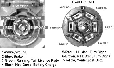
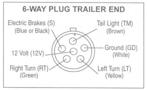
Trailer Wiring Connector Diagrams For 6 7 Conductor Plugs.